Introduction: This walkthrough follows hydraulic force from pump pressure through effective piston area to slide movement and plastic deformation in the workpiece.
Most people who watch a heavy press work notice the same two things: a pressure reading on a gauge and a slide travelling down into a die. It is tempting to treat that gauge number as the press's power, as if a higher reading automatically means a heavier hit on the metal. That shortcut causes a lot of muddled thinking. Pressure and total forming force are related, but they are not the same quantity, and mixing them up makes it hard to explain why one machine shapes thick plate while another with a similar-looking gauge struggles. The chain that links fluid pressure to a deformed workpiece has a few clear links, and once you can name them in order, the everyday confusion mostly disappears.
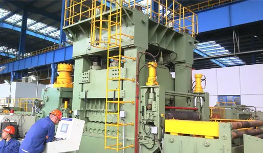
The chain starts at the pump. In an industrial hydraulic press, a pump pushes fluid into a closed circuit, and that fluid does work on a piston. Pascal's principle is the plainest way to describe what happens next: pressure applied to a confined fluid is transmitted through the fluid and acts on every surface it touches, at right angles to those surfaces. A pump does not need to sit next to the cylinder it drives for this to work; the pressure travels through the lines and arrives at the main ram. Anyone who has walked a heavy equipment floor has seen the physical pieces of this chain — the pump unit, the bundled hydraulic lines, the pressure gauge, the main cylinder, and the slide moving below it. What matters for forming is that the circuit has two working ends of very different size. The pump side is small. The main cylinder that drives the slide is large. Force at the ram equals fluid pressure multiplied by the effective area of the piston that the fluid pushes against, so the same pressure acting on a much bigger piston face produces a much bigger push. That multiplication is the whole reason heavy metal forming leans on hydraulics rather than on a direct mechanical shove. There is a trade-off built into it as well: the slide travels more slowly than the pump's small piston, because the same flow of fluid spread across a larger area produces less travel per unit of time. Big force and fast movement come from different parts of the design.
A gauge reading gets quoted in conversation as though it were the machine's capacity, and that is where most of the confusion starts. The number on the gauge describes the condition of the fluid. The number that matters at the die is the load the slide delivers to the workpiece. Two presses can show the same system pressure and still deliver very different forming force, because the size of the cylinder behind that pressure differs. The pressure figure is only half of the story, and on its own it says nothing about how hard the slide can push.
Pressure is force per unit of area, so it describes how hard the fluid pushes on each small patch of surface it contacts. That is an intensity, not a total. A useful everyday comparison is tyre pressure: a bicycle tyre and a truck tyre can run similar internal pressure, yet the truck tyre carries far more load because its contact patch with the road is far larger. Hydraulic systems follow the same logic. Machine designers raise forming force mainly by increasing the working area of the main cylinder, because pressure itself is capped by pump ratings, seal limits and relief valve settings. Pushing pressure higher has a ceiling; making the piston face larger does not hit that ceiling in the same way.
Effective area is the working face of the piston that the fluid pressure actually acts on, measured as a projected area rather than a curved surface. It is the conversion factor between the gauge and the load. Double the effective area at the same pressure and the total force doubles; hold the area steady and halve the pressure, and the force halves with it. This is also why the pressure reading moves around during a stroke. The fluid only develops pressure in response to resistance, so when the workpiece pushes back, the reading climbs until the load is overcome or a relief setting intervenes. Watching the gauge alone shows you intensity; watching the slide shows you what that intensity is actually achieving.
Metal does not bend permanently the moment any load touches it. It first deforms elastically, meaning it springs back when the load is released. Permanent shaping begins once the stress inside the metal exceeds its yield strength, and the material then flows into a new shape. Materials-processing teaching from MIT OpenCourseWare describes this transition through yield criteria, and it adds a second idea that matters here: work hardening. As the metal deforms, it usually becomes harder to deform further, so the stress needed to keep it flowing rises during the stroke. The practical consequence is that the force chain has to be adequate at the hardest point of the operation, not just at the moment the slide first touches the blank. Hydraulic systems fit this job because the force is available through the length of the stroke and can be held at the bottom. A short dwell with the slide pressing on the workpiece gives metal time to flow into the die cavity, which is difficult to arrange with a purely impact-based mechanism. The price of that capability is speed, since slide velocity depends on how much fluid the pump delivers into the cylinder. Force, travel and speed therefore form a set of linked compromises rather than three independent numbers. Reading a press well means reading the pressure, the slide position and the workpiece response together, and treating the gauge as one link in a chain that ends at the metal.
The force chain runs from pump to fluid, from fluid pressure to piston area, from piston to slide, and from slide to the plastic flow of the workpiece. Pressure describes intensity inside the circuit; total forming force describes the load at the die; effective area is what converts one into the other. Keep that sequence in mind and a lot of shop-floor shorthand becomes easier to interpret correctly. Readers who want to see how this plays out in real equipment can look at the hydraulic press machine listings published by EZHONG, a hydraulic press manufacturer working in metal forming, where factory engineering, technical support and project quotations appear as part of the project conversation. As with any heavy equipment, the exact configuration behind those services is settled case by case.
A: A pump pressurises fluid in a closed circuit, and that pressure acts on the face of the main cylinder piston. Because pressure multiplied by effective piston area gives force, a large piston turns modest system pressure into a large push. That push moves the slide, which drives the tooling into the workpiece, while the frame carries the reaction back into the structure.
A: System pressure is an intensity — how hard the fluid pushes on each unit of piston area. Total forming force is the resulting load the slide delivers, and it depends on how large that piston area is. A machine can run at a given pressure and still produce very different forming force from another machine with a larger cylinder.
A: Hydraulic systems multiply force through piston area and deliver it smoothly along the stroke, which suits metal that must be pressed past its yield strength and held while it flows into a die. They can also dwell at the end of the stroke. The trade-off is speed, since slide travel depends on pump flow rather than on a mechanical crank.
Pascal's Principle and Hydraulics
Lecture Notes | Materials Processing | MIT OpenCourseWare